A hydraulic press on a US production line starts drifting out of tolerance. The pump is fine, the cylinder seals are new, and the fluid is clean. The culprit, more often than not, is a directional valve that was specified for on/off switching being asked to do a proportional job. This mismatch shows up constantly in field service calls across the country, and it is the single biggest reason system designers end up researching proportional valve usa options mid-project instead of at the design stage.
A proportional valve does not just open or close. It modulates flow and pressure in response to a variable electrical signal, which means the mechanical output tracks the input command across a range rather than jumping between two states. For anyone specifying hydraulics for motion control, injection molding, mobile equipment, or industrial automation, understanding how these valves work and how to choose between the available types is the difference between a system that performs predictably and one that fights the operator at every setpoint.
What A Proportional Valve Does Differently From A Standard Directional Valve
A standard directional valve is built around two states: energized or de-energized, open or closed. A proportional control valve replaces that binary logic with a continuous relationship between the input signal, typically a 4 to 20 mA current or a 0 to 10 V voltage, and the position of the spool inside the valve body.
The spool position determines both flow direction and flow rate. As the input signal increases, the spool travels further from center, opening a progressively larger metering area. This lets a single valve control acceleration, deceleration, and holding behavior on a cylinder or motor without a separate flow control valve in the circuit.
The practical result is smoother motion, lower shock loading on mechanical structures, and finer control over speed and force. In a plastic injection molding machine, this shows up as consistent shot-to-shot repeatability. In a mobile crane, it shows up as an operator who can feather a load into position instead of jerking it. The tradeoff is complexity: proportional valves need a controller, feedback in many configurations, and a more disciplined approach to specification than a simple solenoid valve.
How A Proportional Directional Valve Works
The working principle of a proportional directional valve depends on whether it is direct operated or pilot operated, but the underlying control loop is consistent across both.
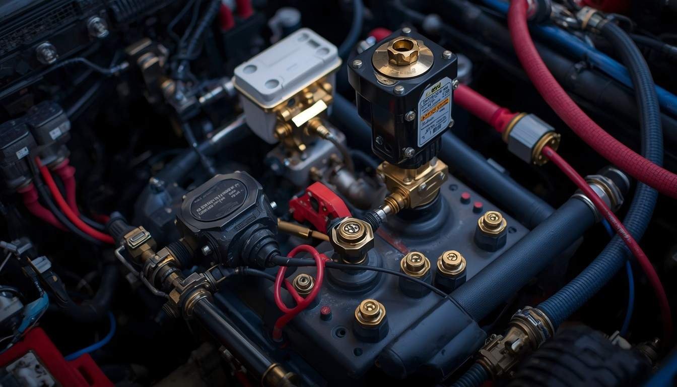
A proportional solenoid receives a command signal from an amplifier or controller. Unlike a switching solenoid, the proportional solenoid produces a force that is directly proportional to the current supplied, not just an on or off pull. That force moves the valve spool against a centering spring, and the spool’s travel opens metering slots machined into the valve sleeve or housing.
In a direct-operated valve, such as the THM HD-4WRE series, the solenoid acts on the main spool directly. These valves are compact and respond quickly, but the solenoid force limits how much flow they can handle, which caps them at lower flow ranges, typically up to around 180 L/min at pressures up to 315 bar.
In a pilot-operated valve, such as the THM 4WRKE Proportional Valve, a small pilot valve stage controls a larger main stage. The pilot valve positions itself in response to the input signal, hydraulic pressure then acts on the main spool, and a position transducer feeds the actual spool position back to the controller in a closed loop. This architecture is what allows pilot-operated proportional valves to handle far higher flow rates, up to roughly 3000 L/min in the 4WRKE range depending on nominal size, while keeping hysteresis and response time within tight tolerances.
The closed-loop position feedback is the detail that separates a genuinely proportional directional valve from a cruder variable-orifice device. Without feedback, spool position can drift with temperature, contamination, or solenoid wear, and the relationship between command signal and actual flow degrades over the life of the machine. With feedback, the controller continuously corrects for that drift, which is why position-controlled proportional valves remain accurate through thousands of duty cycles.
Mounting also affects how a proportional valve integrates into an existing manifold or subplate. Most proportional directional valves, including the direct-operated and pilot-operated series discussed here, follow the ISO 4401 porting pattern common across the industry. This standardization matters more than it sounds, since a designer swapping a solenoid directional valve for a proportional model on an existing machine can often reuse the same subplate and porting, which cuts retrofit cost and downtime considerably.
Response time is the other characteristic worth understanding before spec sheets start blending together. A direct-operated valve typically reaches full stroke faster than a pilot-operated valve of comparable size, simply because there is one less hydraulic stage between the command signal and the main spool. That speed advantage narrows or disappears at higher flow ranges, where a pilot-operated design becomes the only practical option regardless of response time. Matching response speed to the actual dynamics of the load, rather than defaulting to the fastest valve on the shelf, keeps the control loop stable and avoids overshoot on lighter loads.
Types Of Proportional Valves Used In US Hydraulic Systems
Most proportional valves specified in US industrial and mobile applications fall into a handful of functional categories. Each type trades off cost, response speed, flow capacity, and control precision differently, so matching the type to the application matters more than chasing the highest-spec valve available.
Proportional pressure valves regulate outlet pressure in proportion to the input signal and are common in clamping circuits, press force control, and load-sensing pump systems. Proportional flow control valves regulate flow rate independent of pressure changes downstream, which is useful anywhere consistent speed matters more than consistent force. Proportional directional valves, the largest category by application count, control both direction and flow rate simultaneously and are the default choice for motion axes on machine tools, presses, and mobile equipment.
Within directional valves, the direct-operated versus pilot-operated distinction is the first fork in the decision tree, followed by whether the application needs open-loop control or closed-loop position feedback.
| Valve Type | Typical Flow Range | Typical Pressure Range | Response Speed | Best Suited For |
| Direct-Operated Proportional Directional Valve (e.g., HD-4WRE) | Up to approximately 180 L/min | Up to approximately 315 bar | Fast | Smaller axes, machine tools, lower-flow motion control |
| Pilot-Operated Proportional Directional Valve (e.g., THM 4WRKE) | Up to approximately 3000 L/min | Up to approximately 350 bar | Moderate to fast, depending on pilot stage | High-flow presses, mobile hydraulics, heavy industrial motion |
| Proportional Pressure Valve | Application dependent | Set by relief/reducing function | Moderate | Clamping force control, load-sensing circuits |
| Proportional Flow Control Valve | Application dependent | Application dependent | Moderate | Speed regulation independent of load pressure |
The pilot-operated category is where most of the US hydraulic valves market activity sits for higher-power applications, since it scales to flow rates that direct-operated designs cannot reach without oversized solenoids.
How To Choose The Right Proportional Valve For Your Application
Selecting between a proportional control valve and a simpler alternative starts with an honest look at what the machine actually needs to do, not what looks impressive on a spec sheet. A cylinder that only needs to extend and retract at one speed rarely justifies the cost and controller complexity of a full proportional directional valve.
Start with the flow and pressure envelope. Calculate peak flow demand at maximum actuator speed, then check whether a direct-operated valve covers that range or whether the application needs a pilot-operated valve like the 4WRKE series for higher throughput. Undersizing here is the most common specification mistake, since a valve running near its rated flow limit loses control resolution exactly when precision matters most.
Next, decide whether the application needs open-loop or closed-loop spool position control. Closed-loop feedback costs more upfront but pays for itself on any axis where repeatability drifts unacceptably over a duty cycle, such as injection molding shot control or CNC-style motion profiles. Open-loop control can be acceptable on simpler speed-regulation tasks where small drift is tolerable.
Documentation quality matters more than it gets credit for during selection. A valve family with clear, current datasheets, wiring diagrams, and characteristic curves shortens commissioning time considerably compared to one where engineers are reverse-engineering behavior on the bench. Manufacturers that keep their technical content and product documentation current, the kind of ongoing maintenance that content platforms like Rankfast help industrial suppliers manage alongside their catalogs, tend to produce fewer integration surprises for the engineers specifying their valves.
Finally, factor in electrical compatibility and controller availability. A proportional valve is only as good as the amplifier or PLC card driving it. Confirm signal type, whether the valve needs an external amplifier card or has integrated electronics, and whether spare parts and technical support are realistically available in the US market before committing to a supplier.
Duty cycle and environment deserve equal weight in the decision. A valve cycling continuously on a plastic injection molding machine sees very different thermal and contamination stress than one holding a static position on a mobile crane for long stretches between moves. Continuous-duty applications put more strain on the proportional solenoid and any integrated electronics, which pushes the specification toward valves rated for sustained operation rather than intermittent duty. Ambient temperature range matters just as much, since solenoid force output and controller stability both shift as temperature moves away from the manufacturer’s rated band, and mobile equipment operating outdoors across seasonal extremes needs that range checked explicitly rather than assumed.
Filtration requirements tend to get underestimated during specification, even though contamination sensitivity is one of the biggest differences between a proportional valve and a standard directional valve. The tight clearances inside a pilot stage or a closed-loop feedback assembly are far less tolerant of particulate contamination than a simple on/off spool. Reviewing the manufacturer’s recommended fluid cleanliness class alongside the existing filtration on the machine, before the new valve goes in rather than after a failure, avoids a category of field problems that has nothing to do with the valve’s design and everything to do with the fluid feeding it.
Sourcing And Support Considerations For US Buyers
Proportional valves sourced for US installations need to clear a few practical hurdles beyond raw performance specifications. Lead time on pilot-operated, high-flow models tends to run longer than on standard directional valves, since these units carry more precision-machined components and, in many cases, integrated electronics that require calibration before shipment.
Spare parts availability is worth confirming before an order goes in, not after a valve fails in the field. Coils, pilot valves, and position transducers are the components most likely to need replacement over a machine’s service life, and a supplier who stocks these separately from complete valve assemblies will save significant downtime later.
Technical support during commissioning is where the difference between suppliers becomes obvious. A valve that ships with accurate wiring diagrams, characteristic curves, and a technical contact who understands the specific model line will get an axis tuned in a fraction of the time compared to a generic datasheet with no application support behind it.
For teams standardizing on a single proportional directional valve family across multiple machines, working with one manufacturer across the direct-operated and pilot-operated range, rather than mixing suppliers by flow range, tends to simplify both spare parts inventory and operator training.
Proportional valve selection is not a one-time decision. As production requirements shift and machines get retrofitted or upgraded, the same working principle that made a valve the right choice initially should guide the next specification review. Engineers who document flow, pressure, and feedback requirements clearly at the outset put themselves in a far stronger position when it is time to requote, retrofit, or scale the line.
Frequently Asked Questions
How does a proportional directional valve control both flow and direction?
The input signal moves the spool off center in one direction or the other. Spool travel distance sets the metering area, which determines flow rate, while the direction of travel determines which port connects to which, controlling actuator direction at the same time.
What is the difference between direct-operated and pilot-operated proportional valves?
Direct-operated valves use the solenoid to move the main spool directly, limiting flow capacity. Pilot-operated valves use a small pilot stage to hydraulically actuate a larger main spool, enabling much higher flow rates at the cost of a slightly more complex valve body.
Why does the THM 4WRKE use closed-loop position feedback?
Closed-loop feedback uses a position transducer to report actual spool location to the controller, which corrects for drift from contamination, temperature, or wear. This keeps the relationship between input signal and actual flow accurate over long duty cycles.
What flow range can the THM 4WRKE proportional valve handle?
The THM 4WRKE series covers nominal sizes 10, 16, 25, 32, and 35, supporting flow rates up to approximately 3000 L/min and operating pressures up to approximately 35 MPa, depending on the specific size and configuration selected.
When should I choose a proportional pressure valve instead of a directional valve?
Choose a proportional pressure valve when the application needs precise, adjustable force or pressure control, such as clamping circuits or load-sensing pumps, rather than control over actuator direction and travel speed, which is the job of a directional valve.
Do proportional valves need an external amplifier or controller?
Most proportional valves need either an external amplifier card or integrated valve electronics to convert a low-level command signal into the current profile the proportional solenoid requires. Some modern models integrate this electronics package directly into the valve body.
What causes proportional valve control accuracy to degrade over time?
Contamination in the hydraulic fluid, solenoid wear, and temperature swings are the most common causes. Open-loop valves are more exposed to this drift, while closed-loop, position-feedback valves correct for it continuously and hold accuracy longer.
Can proportional directional valves replace separate flow control valves?
Yes, in most circuits. Because a proportional directional valve meters flow through its spool position while also controlling direction, it removes the need for a dedicated flow control valve on that axis, simplifying the circuit and reducing component count.
What should I check before sourcing a proportional valve for a US installation?
Confirm flow and pressure ratings against your actual duty cycle, verify signal compatibility with your controller, and check spare parts availability and technical support for the specific model line before committing, since commissioning delays usually trace back to one of these three gaps.