Directional Control Valve hydraulics is a valve amongst the significant ones which are utilized in the control of movement in hydraulic machine. It directs the pressurized fluid to the required actuator such as hydraulic cylinder or motor and feeds it through various routes depending on the operating conditions of the machine such as extension, retraction, lift, lower and rotation. An adequately planned valve design can eliminate, enhance stability and simplify the manipulation of a hydraulic system.
What is a Hydraulic Directional Control Valve?
A directional valve is a valve that directs hydraulic fluid in a hydraulic circuit. It not only regulates the pressure or flow but also regulates the direction of flow of the hydraulic oil which is also referred to as the direction of hydraulic oil flow direction.
For instance, a valve could be used to send oil to one side of a double-acting cylinder to extend it. When the valve opens, the flow of the oil is inverted, and the cylinder is repressed.
This render the valve as a vital component of machinery when motion control is needed.
In a typical hydraulic control valve, there are:
- Valve body
- Internal spool
- No pressure and return ports
- Actuator or operating mechanism
- Springs and seals
- Working ports the ports that are connected to the actuator.
Design varies according to the pressure, flow, actuator type, control, and machine needs.
How Does a Directional Valve Work?
Working principle: it is based on the change of the flow passages inside.
The spool is used in a spool design where the spool slides in a precision cut bore. The various positions of the spool allow or prevent certain ports from being connected. This alters the direction of the hydraulic fluid.
With a double acting cylinder, one side could be pressurized by the oil at the cap end and the cylinder rod oil return to the oil tank. These connections are reversed if the direction of the move on the spool is the opposite.
The valve regulates the flow of the components depending on the desired movement of the machine.
Directional Control Valve Types
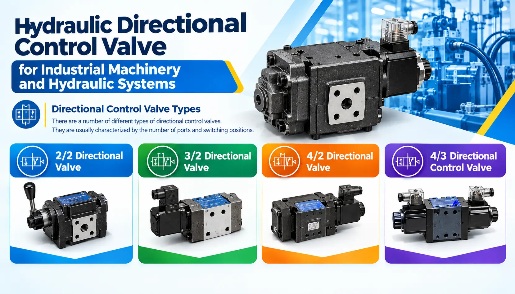
There are a number of different types of directional control valves. They are usually characterized by the number of ports and switching positions.
2/2 Directional Valve
A 2/2 valve is a valve with 2 ports and 2 positions. It’s usually applied to basic flow control (on/off).
3/2 Directional Valve
A 3/2 is a three-port/two-position switch. It can be applied to a circuit that requires limited flow for a single acting actuator.
4/2 Directional Valve
The 4 way directional control valve is a 4-port and 2-position valve. It is normally used in double-acting cylinders where the actuator must move in both directions.
4/3 Directional Control Valve
A 4 / 3 directional control valve is a valve with four ports and three positions. The third (center) position provides the hydraulic designer with more control over the effect of the valve when it is not being actuated.
The flow of the pump and/or the actuator ports may be blocked, connected, or diverted as per the configuration of the center.
Solenoid Directional Control Valve
Solenoid directional control valves use an electrical signal to move the valve mechanism. It is satisfactory for use with automatic machinery that requires a PLC, controller or electrical control system to control the hydraulic circuit.
With solenoid actuation, compared to manual:
- Remote machine control
- Automated sequences
- Faster switching
- A high level of integration with electrical controls is provided.
- Repeatable operation
These should be matched between the control signal and the valve response to the machine’s operating requirements for industrial automation.
Spool Directional Control Valve
A spool directional control valve is a valve that alters the hydraulic flow path by moving a spool. As the spool is moved, it bores holes and ridges inside it which line up with passages inside the spool.
A valve body with this configuration can offer multiple flow connections based on the position of the spool.
The valve performance in a hydraulic circuit is affected by its spool design, center condition, internal leakage, pressure rating and flow capacity.
Directional Control Valve Applications
Directional control valve applications are wide, as hydraulic machines require controlled linear or rotary motion very often.
Common applications include:
- Hydraulic presses
- Machine tools
- Injection molding machinery
- Material handling equipment
- Lifting systems
- Construction machinery
- Agricultural machinery
- Industrial automation equipment
- Hydraulic power units
The valve can regulate the extension and retraction of the cylinder in a hydraulic press. It is able to control lifting, lowering operations in material handling equipment. An electrically operated valve can be used in an automated machine and programmed into a sequence.
Directional Valve for Hydraulic Systems: Key Selection Factors
There are more than just port size considerations when selecting a valve for a hydraulic system.
Consider these factors:
Pressure Rating
The pressure rating of the valve should match the highest pressure to be achieved in the hydraulic circuit.
Flow Capacity
The valve should be capable of allowing the desired amount of flow while maintaining a minimum pressure drop and heat generation.
Number of Ports and Positions
A 3/2, 4/2, 4/3 or other configuration is required depending upon the actuator and circuit configuration.
Actuation Method
There are a variety of machine requirements and options that include manual, mechanical, solenoid, hydraulic pilot and electro-hydraulic.
Spool and Center Configuration
Three-position valves can have a center condition that can impact pump unloading, actuator holding and circuit behavior.
Tips for Better Valve Selection
Prior to the specification of an industrial directional control valve, check:
- Maximum system pressure
- Maximum operating flow
- Required number of ports
- Number of spool positions
- Actuation method
- Hydraulic fluid compatibility
- Mounting arrangement
- Electrical voltage for solenoid versions
- Required response and switching frequency
Also, it is essential to take into account the entire hydraulics circuit instead of choosing the valve individually from the pump, the actuator, the pressure and flow controls.
Important: Valve Size Should Match the Hydraulic Circuit
Too small of a valve will cause excessive pressure loss and heat. If the valve is unnecessarily oversized, it will be more expensive, and this oversizing may not achieve the desired control properties.
Therefore, the pressure and flow ratings of the valve should be compared to the actual operating environment of the machine.
Electrical control specification should also be checked for automated systems prior to choosing a solenoid operated configuration.
Final Considerations
Pump performance is not the only element to consider for good hydraulic performance. That valve that controls that hydraulic power also significantly impacts on the smoothness and predictability of the machine’s movement.
The correct setting of the directional valve should meet the pressure, flow, actuator and control requirements of the system, whether it is a simple cylinder control system or an automatic industrial machine.
When choosing the valve, always consider the machine conditions, don’t simply choose the valve according to the valve size and price. When choosing a hydraulic valve solution for an application, THM Huade can help you with the selection. For product and application assistance, please give us a call today.