A machine builder in Ohio specs a directional valve for a press circuit. A distributor in Texas gets a call asking for a “flow control valve” without any indication of whether the application needs meter-in, meter-out, or bleed-off metering. A maintenance engineer in California pulls a failed valve off a mobile crane and cannot tell from the nameplate whether it was ever a proportional unit or a simple on/off model. These are not rare situations. They happen every week across plants and fleets that run on hydraulic power, and they happen because valve terminology gets used loosely while the underlying function stays very specific.
Anyone sourcing hydraulic valves USA wide runs into the same four families over and over: directional, pressure, flow, and proportional. Each one controls a different variable in the circuit, and picking the wrong type does not just hurt performance. It can shorten pump life, overheat the fluid, or leave an actuator moving at the wrong speed for the job it is doing. This guide walks through what each valve type actually does, how it is built, and where engineers in the field choose one over another.
What A Hydraulic Valve Actually Controls
Every hydraulic circuit needs three things managed at once: which way the fluid goes, how much pressure it carries, and how fast it moves. A valve is built to manage one of those three, or in the case of a proportional valve, to manage more than one with a variable, electronically commanded response.
Confusing these functions is the most common sourcing mistake. A pressure-rated valve body does not automatically mean the valve does directional switching, and a valve that meters flow is not built to hold a system at a set pressure under load. Getting the category right before comparing brands or specs saves a lot of rework later.
Directional Control Valves: Routing Power Through The Circuit
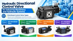
A directional control valve, often shortened to DCV, decides which port the fluid exits through and therefore which way an actuator moves. The simplest version is a two-position, two-way valve that just opens or closes a path. Most industrial applications use four-way, three-position spool valves so a single actuator can extend, retract, or hold in a neutral center.
Spool center configuration matters more than most spec sheets admit. An open-center spool lets flow bypass to tank when the valve sits in neutral, which keeps the pump unloaded but sacrifices instant response. A closed-center spool blocks all ports at neutral, holding the actuator in place under load, which suits presses and lifting applications where drift is unacceptable. A tandem-center spool splits the difference by blocking the actuator ports while still routing pump flow to tank.
Actuation method is the other major decision point:
- Manually operated valves, run by lever or pedal, still show up on mobile equipment where an operator is directly in the loop.
- Solenoid-operated valves switch on an electrical signal and dominate industrial machinery where a PLC or relay logic drives the sequence.
- Pilot-operated valves use a small hydraulic signal to shift a larger main spool, which is standard practice once flow requirements exceed what a solenoid can shift directly.
Mounting interfaces are standardized so valves from different manufacturers can be swapped without redesigning the manifold. In the United States, engineers will see NFPA D03, D05, D07, D08, and D10 mounting patterns referenced alongside their metric ISO 4401 and CETOP equivalents, since the two naming conventions describe the same subplate footprint sizes.
Pressure Control Valves: Relief, Reducing, and Sequence Functions
Pressure control valves protect the circuit and coordinate the order in which different actuators receive flow. They do not route direction and they do not meter speed. Their entire job is holding, limiting, or reducing pressure at a specific point in the system.
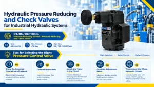
A relief valve is the most common of the group and the one every hydraulic circuit needs somewhere. It stays closed until system pressure reaches a set cracking point, then opens to divert excess flow back to tank, protecting the pump, hoses, and cylinder seals from a pressure spike. A pressure-reducing valve does the opposite job in principle: it takes a higher upstream pressure and drops it to a lower, controlled value for a branch circuit, such as a clamping function that needs less force than the main press cylinder.
Sequence valves add an ordering function. They stay closed until upstream pressure reaches a threshold, then open to send flow to a second actuator, which is how a circuit can be built to clamp a workpiece before a cutting or drilling stroke begins, without any external logic controlling the timing. Counterbalance valves round out the family, holding back flow on the way out of a vertically mounted cylinder so a suspended load cannot free-fall if a hose fails or a directional valve shifts unexpectedly.
Cracking pressure, override characteristics, and response time under transient load are the specs worth scrutinizing here. A relief valve with poor override can let system pressure climb well past its nominal setting under a fast-rising load, which defeats the protection it was installed to provide.
Flow Control Valves: Metering Speed and Motion
A flow control valve manages how fast an actuator moves by restricting or metering the volume of fluid passing through it per unit time, independent of direction or absolute pressure. Three metering arrangements cover almost every application an engineer will encounter.
Meter-in circuits place the flow control valve on the inlet side of the actuator, restricting flow going in and giving direct control over extend or retract speed. This works well when the load resists motion, such as a cylinder pushing against a die. Meter-out circuits place the restriction on the outlet side instead, which handles overrunning loads better, since a load trying to run ahead of the pump, like a descending platform, gets controlled resistance on its way out rather than an uncontrolled surge. Bleed-off circuits route a portion of pump flow to tank before it ever reaches the actuator, which improves efficiency at the cost of less precise speed regulation as load varies.
A related distinction sits between non-compensated and pressure-compensated flow controls. A simple orifice-style flow control valve changes actual flow rate as load pressure changes, since the pressure drop across a fixed restriction varies with the forces acting against it. A pressure-compensated flow control valve adds an internal spool that adjusts the effective orifice size to hold flow constant even as load pressure shifts, which matters anywhere consistent actuator speed under a variable load is a functional requirement rather than a nice-to-have.
Proportional Valves: Where Electronics Meet Hydraulics
A proportional valve usa engineer would install where discrete on/off or manual metering will not deliver acceptable control looks and behaves differently from the three families above. Instead of two or three fixed positions, a proportional valve accepts a variable electrical input, typically a current or voltage signal from a controller, and produces a spool position, and therefore a flow rate, that scales with that signal.
The core enabling technology is the proportional solenoid, which produces a force roughly proportional to input current over a defined stroke range, unlike a standard on/off solenoid that only pulls fully open or releases fully closed. Many industrial and mobile applications now pair that solenoid with a spool position sensor and closed-loop electronics inside the valve body, giving what is typically marketed as a closed-loop proportional valve. This configuration corrects for spool friction, fluid viscosity changes, and manufacturing tolerance in a way an open-loop proportional valve cannot, at the cost of a more complex and higher-priced unit.
Where a proportional valve earns its premium is in applications needing smooth acceleration and deceleration rather than an abrupt shift. Injection molding machines, aerial work platforms, and test rigs simulating road or load input all rely on proportional control to avoid the mechanical shock and hydraulic hammering that a standard directional valve produces on every shift. Response time, hysteresis, and dead band are the specs that separate a serviceable proportional valve from one that will chatter or drift once installed in a demanding duty cycle.
Choosing And Sourcing The Right Valve For A US Application
Matching valve type to application starts with three questions: what variable actually needs controlling, how the actuator load behaves under normal and fault conditions, and what mounting standard the rest of the manifold already uses. An engineer replacing a failed valve on existing equipment should match the NFPA or ISO 4401 mounting pattern first, since a valve with the right function but the wrong footprint will not bolt to the manifold without an adapter plate that adds cost and another leak point.
Documentation matters as much as the hardware once a valve is specified into a design. Datasheets, cracking pressure certificates, and CAD models all need to stay current and easy to pull up when a customer or auditor asks for them, and manufacturers increasingly lean on platforms like Rankfast to keep that kind of technical content and product documentation organized alongside the catalog itself, rather than scattered across static PDFs that go stale after the next revision. That habit turns into a real advantage during supplier evaluation, when a buyer comparing two manufacturers on paper often ends up favoring the one whose specs and application notes are actually easy to find.
The table below summarizes the four families side by side.
| Valve Type | Controls | Common US Standards | Typical Application |
| Directional Control Valve | Flow path / actuator direction | NFPA D03-D10, ISO 4401, CETOP | Cylinder and motor direction switching, press circuits |
| Pressure Control Valve | System or branch pressure | ANSI/ASME pressure classes, manufacturer cracking specs | Relief protection, clamp pressure reduction, sequencing |
| Flow Control Valve | Actuator speed | SAE port sizing, manufacturer flow-rating charts | Cylinder speed metering, feed rate control |
| Proportional Valve | Variable flow/pressure via electronic input | Same mounting standards as DCVs, plus manufacturer response specs | Smooth acceleration, closed-loop motion, mobile controls |
Getting the Selection Right the First Time
Valve selection in a US hydraulic system comes down to matching function to need before comparing price or brand. A directional valve routes power, a pressure valve protects and sequences it, a flow control valve sets its speed, and a proportional valve does all three with an electronic hand on the dial. Engineers who start a spec sheet with the controlled variable, not the part number of whatever failed last time, end up with circuits that run cooler, last longer, and need fewer emergency swaps down the line. As mobile and industrial hydraulics keep folding in more electronic control ahead of events like the NFPA Annual Conference in early 2027, that discipline in valve selection only becomes more relevant, not less.
Frequently Asked Questions
What does NFPA D03 mean on a valve spec sheet?
NFPA D03 identifies a standardized mounting pattern for four-port directional control valves, matching the metric ISO 4401 size 03 and CETOP 3 interfaces. It tells an engineer the valve will bolt to any subplate built to that same footprint, regardless of manufacturer.
When should I use meter-in instead of meter-out flow control?
Meter-in works best when the load resists the direction of motion, such as a cylinder pushing into a die or fixture. Meter-out is the better choice for overrunning loads, like a lowering platform, since it controls the load on its way out rather than letting it run ahead of the pump.
Why does my relief valve allow pressure to spike above its set point?
Most relief valves have some override, meaning pressure continues rising slightly after the valve starts to open before full flow capacity is reached. A valve with poor override characteristics or one sized too small for the transient flow rate will show a larger spike than its nameplate setting suggests.
What is the difference between open-loop and closed-loop proportional valves?
An open-loop proportional valve positions its spool based only on the input signal, with no internal feedback. A closed-loop proportional valve adds a spool position sensor and internal electronics that continuously correct for friction, viscosity, and wear, giving more repeatable flow control at a higher unit cost.
Can a pressure-compensated flow control valve maintain constant actuator speed under a varying load?
Yes. A pressure-compensated flow control valve uses an internal compensator spool to adjust its effective orifice size as load pressure changes, holding output flow close to constant. A standard non-compensated flow control valve will let actual flow, and therefore actuator speed, drift as load pressure rises or falls.
What is a counterbalance valve used for?
A counterbalance valve holds back flow leaving a vertically mounted cylinder so a suspended or overrunning load cannot free-fall if a hose ruptures or a directional valve shifts unexpectedly. It is common on lifts, presses, and any application where gravity can act on the load independent of the pump.
How do I know if a hydraulic system needs a sequence valve?
A sequence valve is needed whenever two actuators must operate in a fixed order using hydraulic logic rather than external controls, such as clamping a workpiece before a cutting stroke begins. The valve stays closed until upstream pressure reaches a set threshold, then opens to send flow to the second actuator.
What causes hysteresis in a proportional valve?
Hysteresis in a proportional valve comes from mechanical friction in the spool and seals along with magnetic effects in the solenoid core, causing the valve to respond slightly differently depending on whether the input signal is increasing or decreasing. Closed-loop designs with position feedback reduce this effect compared to open-loop units.
Are ISO 4401 and NFPA valve mounting sizes interchangeable?
ISO 4401 and NFPA T3.5.1 describe the same physical mounting interfaces using different naming conventions, so a valve built to ISO 4401 size 05 will bolt to a subplate specified as NFPA D05. The dimensions match; only the label differs, though bolt thread type can still vary between SAE and metric versions.